English
  русский
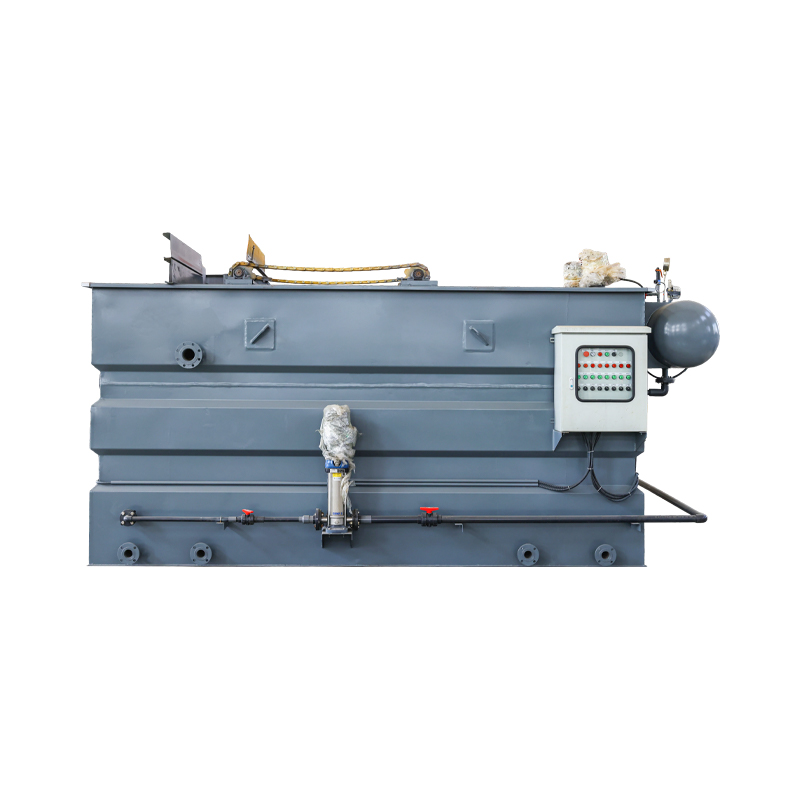
 DAF Systems & Dissolved Air Flotation Pumps: Setup, Treatment & Costs
Content
- 1 What Is a DAF in Wastewater Treatment?
- 2 How DAF Wastewater Treatment Works: Process Stages
- 3 DAF Pump Types: Recycle Pump, Feed Pump, and Selection Criteria
- 4 DAF Clarifier Design: Tank Geometry, Loading Rates, and Key Parameters
- 5 How to Set Up a DAF System: Installation and Commissioning Checklist
- 6 DAF Systems in Oilfield Wastewater Treatment: Onsite vs. Offsite Cost Comparison
- 7 Selecting a DAF Pump Manufacturer: What to Evaluate
What Is a DAF in Wastewater Treatment?
DAF stands for Dissolved Air Flotation — a water and wastewater clarification process that removes suspended solids, fats, oils, greases, and colloidal particles by attaching them to microscopic air bubbles and floating the resulting aggregates to the water surface for mechanical removal. Unlike sedimentation, which relies on gravity to sink dense particles, DAF exploits buoyancy to float low-density contaminants that would otherwise remain suspended or take impractically long periods to settle.
The process works by dissolving air into a pressurized recycle stream of treated water — typically at 4–8 bar — and then releasing that stream back into the flotation tank at atmospheric pressure. The sudden pressure drop causes the dissolved air to nucleate out of solution as a dense cloud of microbubbles, typically 10–100 microns in diameter. These bubbles attach to suspended particles and floc, reducing the effective density of the particle-bubble aggregate well below that of water. The aggregate rises to the surface and forms a floating sludge layer — called float or skimmings — which is continuously removed by a mechanical skimmer.
DAF in water treatment and wastewater treatment is applied across an exceptionally wide range of industries: municipal drinking water clarification, food and beverage processing effluent, paper and pulp mill wastewater, textile dyehouse effluent, oil refinery produced water, aquaculture recirculation systems, and oilfield produced water treatment. Its particular strength is in applications where the target contaminants have a specific gravity close to or less than 1.0 — fats, oils, fibers, and biological floc — where sedimentation is slow and unreliable.
How DAF Wastewater Treatment Works: Process Stages
A complete DAF wastewater treatment system processes influent through several sequential stages. Understanding each stage is necessary for correct system design, chemical dosing, and operational troubleshooting.
Stage 1 — Pre-Treatment and Equalization
Raw wastewater entering a DAF system typically passes through screens or strainers to remove gross solids that would otherwise foul the recycle pump and saturator. For batch or variable-flow industrial processes, an equalization tank upstream of the DAF unit buffers flow and contaminant load variations, preventing hydraulic shock and chemical dosing instability that reduce separation efficiency.
Stage 2 — Chemical Coagulation and Flocculation
Most DAF applications require chemical pre-treatment to destabilize colloidal particles and aggregate fine suspended solids into floc large enough for bubble attachment. Coagulants — typically aluminum sulfate (alum), ferric chloride, or polyaluminum chloride (PAC) — are dosed at a rapid-mix point to neutralize the negative surface charge on colloidal particles. Flocculants — anionic or cationic polyacrylamide polymers — are then dosed in a gentle-mix zone to bridge individual coagulated particles into larger, stronger floc structures. Floc size, density, and strength are the primary determinants of DAF separation efficiency, making chemical selection and dosing optimization a critical design and operational parameter.
Stage 3 — Pressurization and Air Dissolution
A portion of the clarified DAF effluent — the recycle stream, typically 10–50% of the feed flow rate — is pressurized by the DAF recycle pump and fed into a pressure vessel called the saturator or dissolution tank. Compressed air is injected into the saturator, where it dissolves into the water under pressure according to Henry's Law. The saturated recycle stream is held under pressure until directed to the flotation tank inlet.
Stage 4 — Flotation and Skimming
The pressurized recycle stream is released through a pressure reduction valve into the flotation tank, where it contacts the incoming chemically treated feed water. Microbubbles nucleate instantaneously and attach to floc particles, which rise to the surface over the tank's hydraulic retention time — typically 15–30 minutes in conventional DAF designs, reduced to 3–8 minutes in high-rate units. A chain-and-flight or rotating beach skimmer continuously removes the accumulated float sludge into a sludge collection trough. Clarified water exits from the tank base through submerged effluent ports.
Stage 5 — Sludge Handling
DAF float sludge typically has a solids concentration of 2–8% dry solids by weight — significantly more concentrated than clarifier underflow sludge from equivalent sedimentation processes. This concentration advantage reduces downstream sludge dewatering equipment size and operating cost. Float sludge is commonly thickened further in gravity belt thickeners or centrifuges before disposal, composting, anaerobic digestion, or — in food processing applications — recovery as animal feed ingredient.
DAF Pump Types: Recycle Pump, Feed Pump, and Selection Criteria
The dissolved air flotation pump — or DAF pump — is the component most directly responsible for system performance. Two distinct pump duties exist within a DAF system, each with different performance requirements, and selecting the correct pump type for each duty is fundamental to reliable operation.
The DAF Recycle Pump
The DAF recycle pump pressurizes the clarified effluent recycle stream to the saturator operating pressure — typically 4–8 bar (60–120 psi). This is the most critical pump in the system; its performance directly determines the quantity and quality of microbubbles generated, which in turn controls separation efficiency.
Key selection criteria for the recycle pump include:
- Multi-stage centrifugal design: The pressure requirement (4–8 bar) combined with the moderate flow rates typical of recycle streams (10–50% of feed) places the duty point squarely in multi-stage centrifugal pump territory. Single-stage pumps are insufficient for pressure; positive displacement pumps are generally over-specified and more expensive to maintain.
- Tolerance of entrained air: The recycle stream at the pump inlet may contain residual dissolved air coming out of solution. Conventional centrifugal pumps cavitate under these conditions; DAF-specific recycle pumps are designed with enlarged impeller eye areas, reduced NPSH requirements, and sometimes self-priming capabilities to handle gas-liquid mixtures without vapor lock.
- Variable speed drive: Fitting the recycle pump with a variable frequency drive (VFD) allows recycle flow rate — and therefore bubble generation rate — to be adjusted to match feed flow and contamination load variations, improving efficiency and reducing energy consumption at part load.
- Materials of construction: For clean water or municipal applications, cast iron with stainless internals is standard. For food processing, pharmaceutical, or high-chloride industrial effluent, all-stainless 316L construction is required to prevent corrosion product contamination of the process stream.
Feed and Transfer Pumps
The feed pump transfers raw or pre-treated wastewater from the equalization tank to the DAF unit at a controlled, consistent flow rate. Because the feed stream may contain suspended solids, fibrous material, or biological content, feed pumps are typically non-clog centrifugal, progressive cavity, or submersible sewage pump designs with open or vortex impellers that pass solids without blocking. Unlike the recycle pump, the feed pump operates at low to moderate pressure — typically 0.5–2 bar — sized purely for flow delivery and minor static head.
DAF Clarifier Design: Tank Geometry, Loading Rates, and Key Parameters
The DAF clarifier — the flotation tank itself — is the central process vessel of the system, and its geometry determines the hydraulic retention time, bubble-particle contact efficiency, and float sludge removal performance that collectively define overall system throughput and effluent quality.
Hydraulic Surface Loading Rate
The primary sizing parameter for a DAF clarifier is the hydraulic surface loading rate (also called overflow rate or surface hydraulic loading), expressed as flow per unit of tank surface area. Conventional DAF units are designed for surface loading rates of 3–6 m³/m²/hr; high-rate DAF designs using lamella tube modules or optimized inlet distribution can achieve 10–15 m³/m²/hr or higher. Exceeding the design surface loading rate causes hydraulic short-circuiting, reduced retention time, and carryover of float sludge into the effluent.
Tank Geometry Options
DAF clarifiers are manufactured in rectangular and circular configurations. Rectangular tanks are standard for larger installations — they allow straightforward chain-and-flight skimming, accommodate inlet distribution baffles efficiently, and can be constructed in modular sections for site-built large systems. Circular DAF clarifiers use rotating skimmer arms and are compact and cost-effective for smaller flow rates; they are common in package plant configurations for food processing and smaller municipal applications.
Contact Zone and Separation Zone
A well-designed DAF clarifier separates the tank hydraulically into two functional zones. The contact zone at the inlet is where pressurized recycle water mixes with the chemically treated feed, maximizing bubble-particle collision and attachment. The separation zone occupies the majority of the tank length, providing the quiescent hydraulic conditions necessary for bubble-particle aggregates to rise to the surface without turbulent disruption. Baffles separating these zones are a critical design detail; inadequate separation allows inlet turbulence to disrupt rising float in the separation zone, degrading effluent quality.
How to Set Up a DAF System: Installation and Commissioning Checklist
Setting up a DAF system correctly at installation determines whether the unit achieves its design performance from day one or requires months of troubleshooting to reach stable operation. The following checklist covers the critical steps for new DAF unit installation and initial commissioning.
- Confirm civil and structural requirements: The DAF tank, chemical dosing skids, and recycle pump set must be installed on a level, structurally adequate concrete base. A full DAF system — tank, water, sludge, and ancillary equipment — exerts substantial point loads; structural engineering review of the base slab is required for any system above 20 m³/hr capacity.
- Install and align the recycle pump: Mount the recycle pump with correct suction and discharge pipe supports to prevent stress on pump flanges. Confirm NPSH available at the pump suction exceeds NPSH required by at least 0.5–1.0 m margin across the operating flow range. Misalignment between pump and motor is the primary cause of premature seal and bearing failure.
- Commission the saturator: Fill the saturator with clean water and pressurize to operating pressure with the air supply connected. Check for leaks at all flanged and threaded connections. Verify the air injection rate using the system's rotameter or flow controller, targeting an air-to-water ratio of 5–10 mL air per liter of recycle water at operating pressure for most applications.
- Set the recycle flow rate: Commission the recycle pump at the design recycle ratio (typically 15–30% of feed flow) using the recycle control valve. Confirm stable pressure at the saturator — pressure fluctuations indicate pump cavitation, air lock in the suction line, or an undersized recycle valve.
- Optimize chemical dosing: Begin with jar test results as the starting point for coagulant and flocculant doses, then adjust based on actual effluent turbidity, total suspended solids, and float sludge quality during initial operation. Fine-tune rapid-mix and gentle-mix retention times if the system includes inline mixing reactors.
- Set skimmer speed and sludge draw-off: Adjust skimmer travel speed to maintain a consistent float sludge blanket depth of 50–150 mm on the tank surface. Too slow allows float to re-mix into the water; too fast dilutes float sludge with clarified water, increasing sludge volume and downstream handling cost.
- Verify effluent quality against design targets: Sample clarified effluent for TSS, turbidity, BOD, and oil and grease (as applicable to the wastewater type) after 30–60 minutes of stable operation. Compare against design guarantee values and commissioning acceptance criteria before signing off the installation.
DAF Systems in Oilfield Wastewater Treatment: Onsite vs. Offsite Cost Comparison
In oilfield and upstream oil and gas operations, produced water and flowback water represent some of the highest-volume and most challenging wastewater streams encountered across all industries. DAF systems are widely used as a primary treatment stage for oilfield wastewater — removing dispersed and emulsified oil, suspended solids, and naturally occurring radioactive material (NORM) scale before discharge, reinjection, or further treatment for beneficial reuse.
Operators managing produced water face a fundamental decision: treat wastewater onsite using installed or mobile DAF and associated treatment equipment, or truck or pipe wastewater offsite to a commercial disposal or treatment facility. This decision has major cost, liability, and operational implications.
Onsite Treatment Cost Structure
Onsite oilfield wastewater treatment using DAF systems involves the following primary cost categories:
- Capital equipment: A mobile or skid-mounted DAF unit suitable for oilfield produced water treatment — typically 50–500 m³/day capacity — ranges from USD 80,000 to USD 400,000 depending on capacity, materials specification, and ancillary systems included. Larger permanent installations for high-volume fields scale significantly beyond this.
- Operating cost per barrel: Onsite DAF treatment of oilfield produced water typically costs USD 0.50–2.50 per barrel treated, encompassing energy, chemicals, labor, and maintenance — with the exact figure heavily dependent on water chemistry, treatment target, and local energy cost.
- Residuals management: Onsite treatment generates a concentrated oil-laden sludge that must be characterized and disposed of as a regulated waste — typically at a cost of USD 50–150 per ton depending on NORM content and regional disposal infrastructure.
Offsite Treatment and Disposal Cost Structure
- Trucking cost: In regions without produced water pipeline infrastructure — common in unconventional shale plays — trucking to Class II disposal wells or commercial treatment facilities costs USD 3–12 per barrel depending on haul distance, road conditions, and regional truck availability. At 10,000+ barrels per day of produced water, trucking costs can exceed the value of oil production from the same wells.
- Disposal well injection fees: Commercial saltwater disposal (SWD) well tipping fees typically run USD 0.25–1.50 per barrel excluding transportation, subject to regional market rates and regulatory constraints on injection volumes.
- Liability and compliance exposure: Offsite disposal transfers immediate handling liability to the disposal facility, but the generator retains long-term liability under "cradle-to-grave" frameworks such as RCRA for any subsequent environmental impact from the disposal site — a liability that is difficult to quantify and impossible to eliminate entirely.
Break-Even Analysis and Decision Framework
The economic break-even point between onsite DAF treatment and offsite disposal is primarily driven by produced water volume and transportation distance. At volumes above approximately 2,000–5,000 barrels per day and trucking distances exceeding 30–50 miles, onsite treatment consistently generates a lower total cost per barrel than offsite disposal — even accounting for capital amortization and the full onsite operating cost stack. Below these thresholds, or in plays with established low-cost pipeline takeaway infrastructure, offsite disposal remains competitive on a pure cost basis.
Beyond direct cost, operators increasingly factor water reuse value into the analysis. Treated produced water meeting specifications for hydraulic fracturing reuse eliminates freshwater acquisition costs — which in water-stressed basins such as the Permian can reach USD 1.50–3.00 per barrel for sourced freshwater — fundamentally changing the economics in favor of onsite treatment even at lower produced water volumes.
Selecting a DAF Pump Manufacturer: What to Evaluate
Selecting a DAF pump manufacturer — whether for the recycle pump specifically or for a complete DAF system package — requires evaluating technical capability, application experience, and after-sales support rather than equipment price alone. A recycle pump that fails to maintain stable saturator pressure, or cavitates under variable feed conditions, will compromise DAF performance regardless of how well the rest of the system is designed.
Key evaluation criteria for DAF pump manufacturers and system suppliers include:
- Application-specific pump design: Confirm that the supplier's recycle pump is specifically engineered for DAF service — not a standard booster pump repurposed for the duty. DAF-specific designs address dissolved gas handling, low-NPSH operation, and the pressure-flow characteristics of saturator service that standard pump ranges do not.
- Industry references: Request references from installations in the same industry sector and at comparable flow rates. A manufacturer with extensive municipal water treatment references may not have the application knowledge needed for food processing effluent or oilfield produced water, where chemistry and contaminant types differ significantly.
- Spare parts availability and lead times: The recycle pump is the single highest-consequence failure point in a DAF system — if it stops, the entire treatment process stops. Confirm that wear parts (mechanical seals, impellers, bearings) are held in stock and available for rapid dispatch, not manufactured to order with 8–12 week lead times.
- Process guarantee: A reputable DAF system manufacturer will provide a process performance guarantee — specified effluent TSS, oil and grease, or turbidity values — backed by contractual remedies, not merely equipment specification compliance. This aligns the supplier's interests with achieving actual treatment outcomes rather than simply delivering hardware.
Let's Cooperate with Yixing Hengye Environmental Protection
Contact UsRelated Products


- Product Categories
- Sludge Dewatering Machine
- Roller Filter
- Dissolved Air Flotation Machine(DAF)
- Rotary Mechanical Bar
- Dosing Device
- Aerator
- Biological Packing Material
- Other Wastewater Treatment Equipment
- Contact Us
-
-
[email protected]

[email protected] -
+86-13812201185

-
+86-13812201185

-
No. 20, Saite Road, Gaoyao Village, Gaocheng Town, Yixing City, Wuxi City, Jiangsu Province, China

-